RaspberryPi Simulator
The RaspberryPi Simulator is a plugin used for the simulation of simple circuits using a RaspberriPi. It can simulate series circuits made of leds, buttons and LCDs. The code to be runned on the RaspberryPi is written in the Application tab, and the only supported language is NodeJS. So, the basic 2 components of this plugin is the project and the schema of the circuit.
Steps to use the RaspberryPi Simulator
You can use the RaspberryPi Simulator by following the next steps.
1. Connection
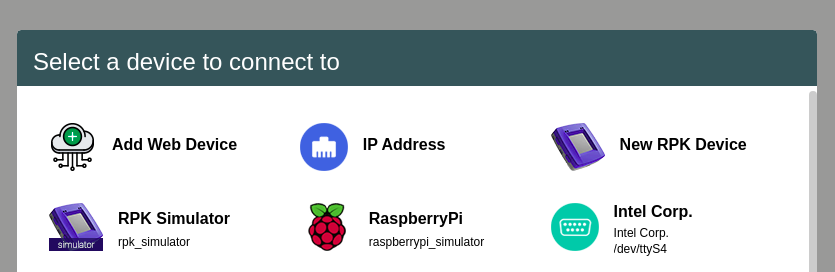
If you are connected to another device, disconnect from it. After that, press the CONNECT button in the headbar, and afterwards choose the “RaspberryPi” that runs on the board raspberrypi_simulator. This simulates a connection to a phisical board.
2. RaspberryPi Simulator tab
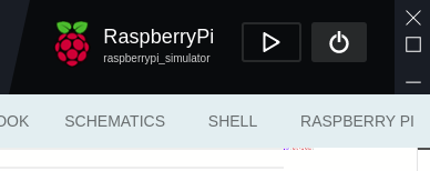
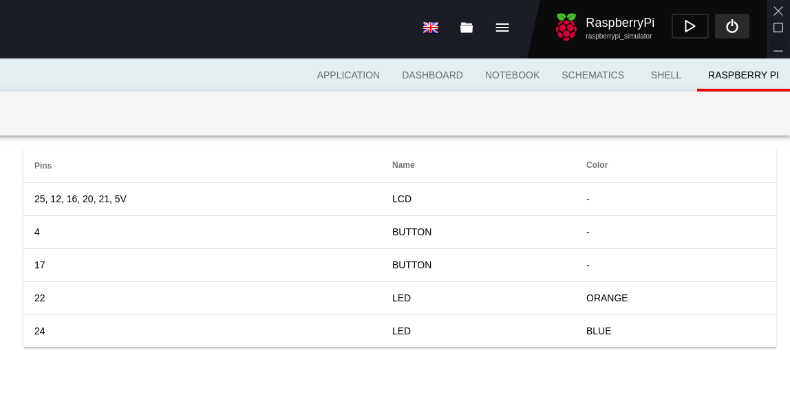
After you connect to the RaspberryPi Simulator board, a new tab will appear on the right in the tab list, named RASPBERRY PI. This tab has a structure of three components:
- The button to open the list of examples
- It is located right under the tab list. After you press the button, a list of examples will be opened on the left side. At the top of the list will be a button LOAD SCHEMA used to load your own schema. We will discuss about that later.
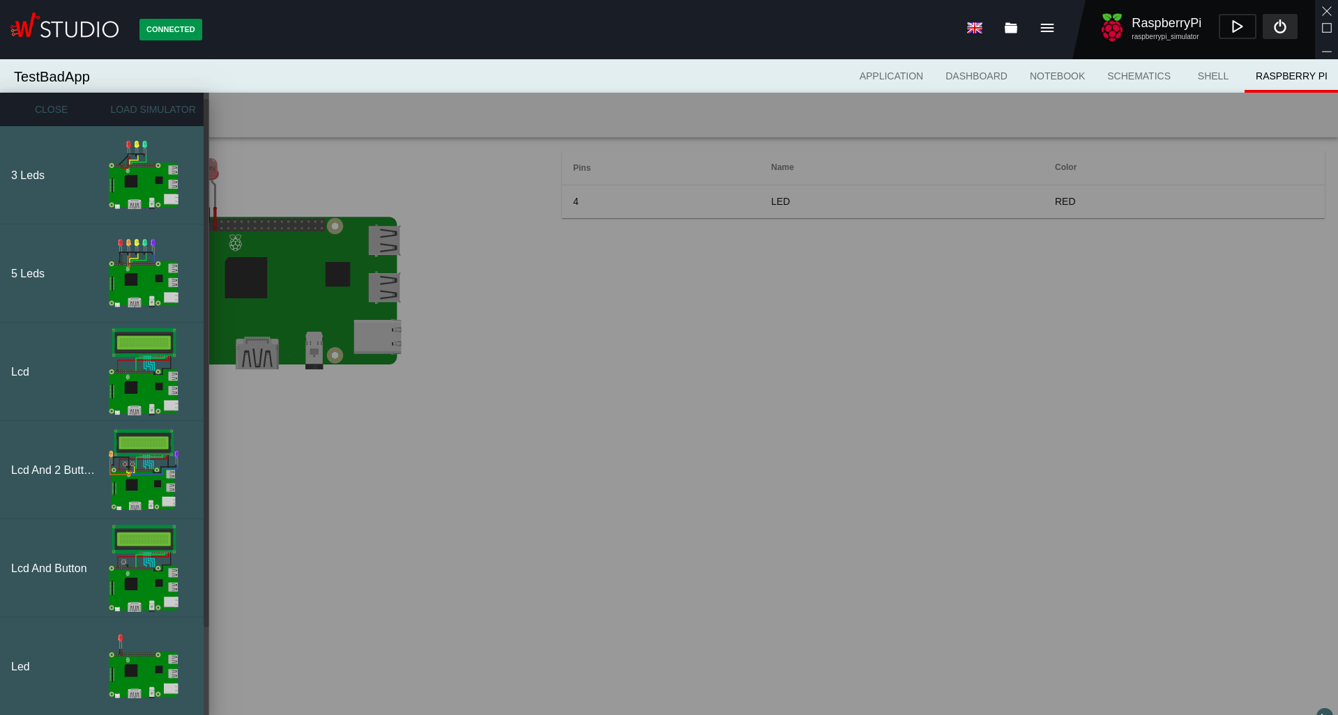
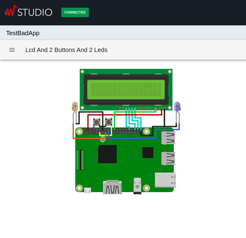
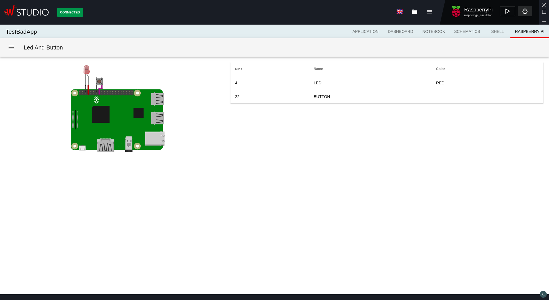
- The circuit image
- It is located on the left side of the window. The image is interactive, meaning that the leds can turn on, the buttons can pe pressed, and so on.
- The table of connections
- It is located on the right side of the window. Here you will see a simplified structure of the connections, so you can see which pins are connected in order to know how to use the components.
3. Load a project and run it
After you got accostumed to the RaspberryPi Simulator tab, you can load a project written in NodeJS. There are only 2 libraries available at the moment, in order to control the GPIO pins on the RaspberryPi and the LCDs.
Afterwards, you can just press the RUN button and the code will start to execute. Also, the console remains active in the RaspberryPi Simulator tab, so you can see the evolution of your code while interacting with the schema loaded.
Load your own schema
- The RaspberryPi Simulator plugin runs on schemas created with Fritzing. A schema has 2 components:
- the image of the circuit, saved in a SVG format
- the netlist with the connections, saved in a XML format
In order to create your own schema, you can follow the next steps.
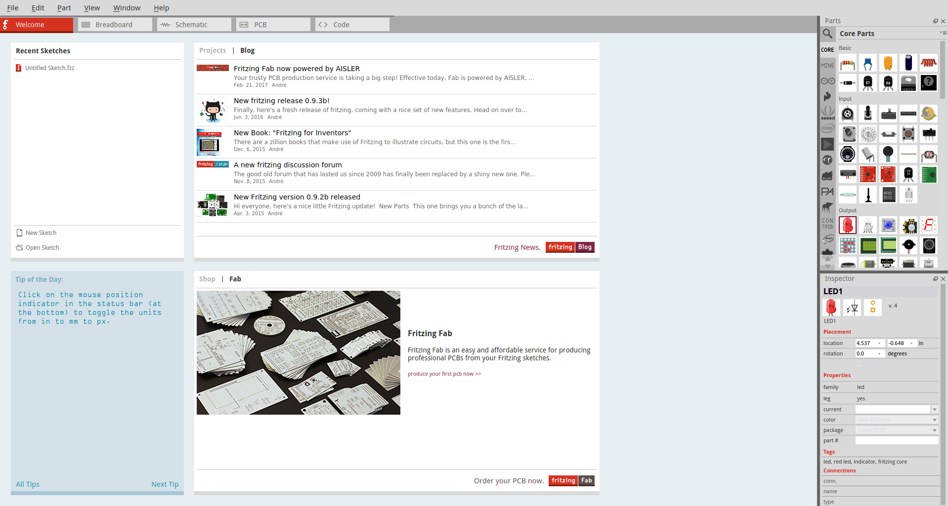
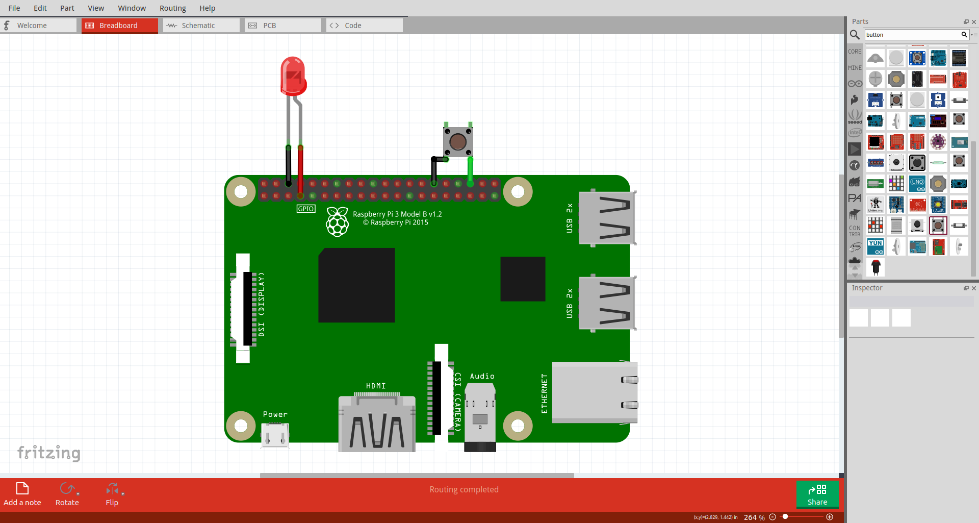
1. Download and open Fritzing
You can access the Fritzing download page by clicking here. After you download the application, open it. You will see the below window.
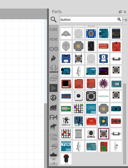
2. Add components
After you open the app, you have to go to the Breadboard tab. From this tab you will export the files required for the schema, meaning the SVG image and the XML netlist. On the right-top side you will see a window with components. From there you can search for the desired the components. The available components that are recognized by the simulator are:
- RaspberryPi 3
- Pushbutton
- LED
- LCD 16x2
In order to place a component with just have to drag and drop it on the main panel from the Breadboard tab.
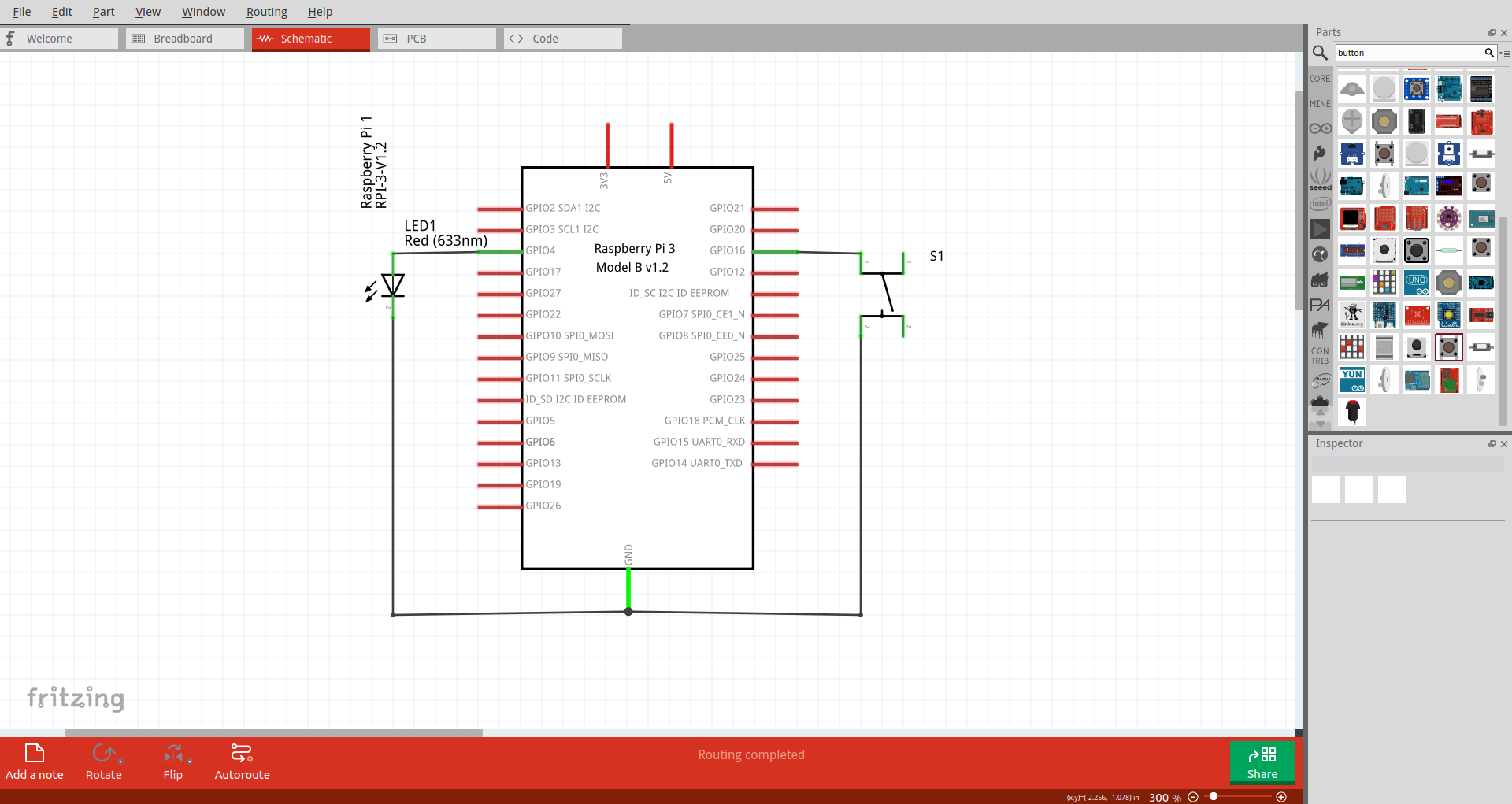
3. Make connections
After you’ve placed all the required components, you have to acces the Schematic tab. There you will see all components and you can make the connections between them. After the connections are done, you have to go back on the Breadboard tab and make the phisical connections again. There will be dotted lines that correspond to the connections from the Schematic tab. Also, you can edited the components from the window on the right-bottom. For example, you can change the color of the led, or the color of the wire.
4. Export from Fritzing
Attention! In order to export the files from the schema created, you have to be on the Breadboard tab.
- To export the required files for the schema, you have to follow 2 steps:
- export the SVG file: File -> Export -> as Image -> SVG…
- export the XML netlist: File -> Export -> XML Netlist…
You have to save the files on your computer in an easy accesible location, because you will need the afterwards.
5. Import to Wyliodrin STUDIO
- To import the files just created with Fritzing, you have to follow the next steps:
- access the RASPBERRY PI tab
- click on the button to open the list with examples
- press LOAD SCHEMA, and a pop-up will appear on your screen
- give a name to your schema if you want
- press ADD SVG FILE and choose your just-created SVG file
- press ADD XML NETLIST and choose your just-created XML netlist
- press UPLOAD
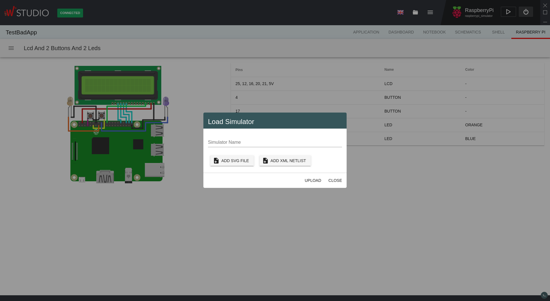
If all the steps are followed correctly, your schema should appear on the main view, along side with the table of connected components.
Libraries for RaspberryPi Simulator
In the RaspberryPi Simulator you can almost fully use two main libraries: onoff.GPIO and LCD. The usage of these libraries is the same as the usage on phisical boards. The only difference is that not every function is available. Bellow you can see a list of available function for the 2 libraries. To see more of the usage for these libraries you can access one of the links bellow:
- onoff.GPIO:
- create(pin, state) -> creates an object from which you can control the GPIO pins on the RaspberryPi. The state parameter is a string and it indicates the type for the pin input/output
- readSync() -> return the value readed by the pin 1/0
- writeSync(value) -> outputs on the GPIO pin the selected value 1/0
- direction() -> return the state of the pin
- setDirection(state) -> change the state of the pin
- activeLow() -> return the state of the activeLow property of the pin
- setActiveLow(value) -> change the activeLow property on the pin
- LCD:
- create(object) -> it creates an object in order to interact with the LCD. The object contains 4 properties: rs, e, data, cols, rows
- print(string) -> print the given string on the screen starting from the cursor current position
- clear() -> clears the LCD screen
- home() -> sets the cursor on the cell 0x0 on the LCD
- setCursor(row, col) -> sets the cursor on the row line and col column
- scrollDisplayLeft() -> scrolls the display one position tp the left
- scrollDisplayRight() -> scrolls the display one position tp the right
- close() -> close the connection with the LCD and free the assigned pins
Attention! LCD library only supports the 16x2 LCD!
Code examples
Bellow are 2 code examples on how to use the onoff.GPIO library and the LCD library.
onoff.GPIO example
The schematic associated to this code should have a led connected to GPIO4 pin on the RaspberryPi and to the GND pin, and a button connected to the GPIO22 pin and to the 3V pin.
This program will wait 2 seconds, will turn the led on, the will wait another 2 seconds and will turn it off. Afterwards, it will remain in the while loop while the button is not pressed.
var Gpio = require("onoff").Gpio;

var led = new Gpio(4, "out");
var button = new Gpio(22, "in");

sleep(2000);
led.writeSync(1);
sleep(2000);
led.writeSync(0);

while(button.readSync() === 0) {
        sleep(1000);
}

console.log("onoff.Gpio tutorial finished!");
LCD example
- The schematic associated to this code should have a LCD connected as it follows:
- VSS connected to the GND pin
- VDD connected to the 5V pin
- RS connected to the GPIO25 pin
- E connected to the GPIO2 pin
- DB4 connected to the GPIO23 pin
- DB5 connected to the GPIO17 pin
- DB6 connected to the GPIO18 pin
- DB7 connected to the GPIO22 pin
This program will write the “Hello world, from the LCD!” string on the LCD. Because it won’t fit, we will scroll the display to the left for 10 times, and the we will clear the display. At the end, we close the connection to the LCD.
var LCD = require("lcd");
var lcd = new LCD({rs: 25, e: 2, data: [23, 17, 18, 22], cols: 16, rows: 2})

lcd.print("Hello World, from the LCD!");

sleep(2000);

for (var i = 0; i < 10; i ++) {
    sleep(1000);
        lcd.scrollDisplayLeft();
}

sleep(1000);
lcd.clear();

lcd.close();

console.log("LCD tutorial finished!");